
You may not realize it yet, but you need PCIe 5.0 technology and here’s why. With 5G smartphones poised to launch in 2019, consumers are likely to see a substantial increase in digital bandwidth on their mobile devices. While 4G LTE technology could hit a maximum theoretical throughput of 1Gbit/s, 5G will offer users a bandwidth of well over 10x that speed. While we all love increased network speed, there is an implied assumption that the backbone speeds of the internet will keep up with this rising demand placed upon it by millions of new 5G devices. And, it isn’t just mobile devices that are driving the need for network providers to quickly stay ahead of the growing, on-demand, content driven environment we are living in today.
In April 2018, Cignal AI increased its 400G adoption forecast [1] indicating that it will soon start to replace 100G and 200G based network deployments. This has significant implications for PCI Express technology since PCIe is the main interface bridging the IO gap between Server CPUs and the host bus adapters that create the 400G network.

Figure 1. 400G adoption to dominate Internet bandwidth speed by 2021.
PCI Express 4.0 technology, operating at speeds of up to 16Gb/s, is a substantial improvement over PCIe 3.0 devices offering double Gen3 performance. Nevertheless, when it comes to supporting 400G host bus adapters, recently released endpoint devices that support PCIe 4.0 won’t be able to keep up and it’s all in the numbers. To meet the bandwidth requirements of a 400G Ethernet link, you must have a minimum of 50 GBytes/s in each direction over the interface to the CPU. With a full 16 lanes of PCIe 4.0 at 16Gbit/s, you have a maximum throughput of only ~32GBytes/s per direction. Hence, this is one of the main reasons behind the PCIe 5.0 buzz. At 32Gbit/s per lane, PCIe 5.0 technology delivers a whopping 64GBytes/s over 16 lanes in each direction for a total link bandwidth of ~128GB/s. This is more than enough to meet the needs of 400G Ethernet.

Figure 2. PCIe 5.0 Technology was defined with 400G support as a key requirement of the specification.
Perhaps not surprisingly, it isn’t just 400G that is driving the need for increased PCIe Express bandwidth. Many AI applications are being deployed in the cloud environment, with the use of co-processors including graphic processing units or GPUs. The GPUs advanced vector processing capabilities were first applied to 3D game rendering, fueling the growth of a multimillion-dollar gaming industry. But now, those high-end computational abilities of the GPU are being harnessed more broadly to accelerate computational workloads found in financial modeling, leading-edge scientific research, and artificial intelligence. Likewise, improvements in solid-state storage economics are driving big changes in computer architecture, and, as the speed of NAND based storage increases, you also see an increased need for more bandwidth over the server’s IO interface.
All these significant trends were the main reason that the Peripheral Component Interconnect Special Interest Group (PCISIG) embarked upon a very aggressive schedule to publish the PCIe 5.0 specification in 2019. PCIe 5.0 (or Gen5) represents the technology that is needed by the computer, data center, and ultimately the 5G wireless industry to enable the next generation of mobile and desktop applications.
So, what is PCI Express 5.0 and how does it compare to PCI 4.0? One way I like to think of PCIe 5.0, is that it is basically PCIe 4.0 with features that make it possible for the technology to operate at 32GT/s. The PCISIG uses GT/s or giga transfers per second to describe PCIe speed as opposed to giga bits per second to acknowledge that the PCIe protocol has some overhead that cuts into the raw data throughput. Thus, some things about PCIe 5.0 are very much the same as what was in the PCIe 4.0 specification. These similarities include:
- NRZ signaling
- 128/130 bit encoding
- Transmitter based de-emphasis (defined in the spec as P0-P10)
- Backward compatibility (both mechanical and electrically compatible with PCIe 1.1, 2.0, 3.0 and 4.0)
- Same connector pinout as earlier generations of PCIe
- Same BER target of 1x10-12
- Same TX Voltage and Jitter parameters as PCIe 4.0.
Nevertheless, there obviously must be some substantial differences between PCIe 4.0 & 5.0 and yes, there are big ones. The key thing to remember is that the PCIe 5.0 spec writers worked hard to minimize the changes to primarily comprehend those things necessary to enable the speed bump to 32GT/s. These changes include:
- A new channel definition that can accommodate up to about -37dB of loss at the Nyquist frequency of 16GHz
- A post equalization minimum eye height of 15mV and a minimum eye width of 9.375ps (0.3UI)
- A reference equalizer consisting of new CTLE performance combined with a 3-tap DFE
- A new reference CDR that has a second order response
- A TX PLL Loop BW phase jitter limit of 0.15ps (RMS)
- A CEM connector definition limited to a surface mount footprint only (no through-hole connector is approved).
One of the key assumptions going into the PCIe 5.0 specification is with the way that the transmitter and receiver components are validated. This assumption was based on the premise that the overall test method used to validate a PCIe 4.0 transmitter and a PCIe 4.0 receiver could be substantially leveraged to test PCIe 5.0 devices operating at 5.0 GT/s.
For example, if we consider testing a PCIe 5.0 ASIC transmitter, the PCIe 5.0 specification allows you to have a break out channel that allows you to conveniently access the high-speed PCI Express 5.0 signals.

Figure 3. An example of PCIe 5.0 transmitter testing using frequency domain compensation or CTLE compensation of the breakout channel losses using Keysight’s N5465A Infiniium Waveform Transformation Toolset.
As shown by Figure 3, the loss of the breakout channel must be compensated for in the transmitter measurements. To do this, either one or two approaches may be applied. The primary method requires that you capture the S-Parameters of the breakout channel and then use a toolset such as in Figure 3 to “de-embed” the loss effects from the transmitter waveform captured on your oscilloscope. In cases where you do not have access to the S-parameters of the ASIC’s break-out channel or if the break-out channel has more than about -6dB of loss at 16GHz, you have the option of using the PCIe 5.0 CTLE equalization curves used in the reference receiver definition to help compensate for your test device’s break-out channel loss. The PCISIG suggests that you may want to try both approaches and then use the method which gives you the optimal result. The reason for considering a continuous time linear equalizer (CTLE) based compensation (as opposed to S-parameters) is due to the tendency of traditional de-embedding approaches to amplify noise. To limit this noise amplification, the PCIe 5.0 specification limits the de-embed bandwidth of your measurement to no more than 32GHz.
The noise of measurement instrumentation is a substantial concern for PCIe 5.0 devices because the minimum bandwidth of the oscilloscope used to test a PCIe 5.0 device must be at least 50GHz per the PCIe 5.0 specification and since the minimum eye height after equalization is only 15mV. As real time oscilloscope bandwidth increases, the tendency is for noise to proportionally increase as well. To maximize your transmitter’s performance, you want to ensure your transmitter test instrumentation has the lowest noise available (see Figure 4). Oscilloscopes with an improved noise floor translate directly into larger measured PCIe 5.0 eyes and more overall confirmable margin for your PCIe 5.0 devices.
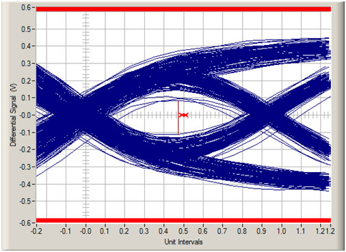
Figure 4. A 32GT/s PCIe 5.0 eye measured with a Keysight 50GHz UXR real-time oscilloscope (which was designed specifically to enable more accurate measurements for faster technologies such as PCI Express 5.0 ). This shows in context an eye height at the near end of the transmitter. After a -38dB channel is applied, this eye will be completely closed, relying on advanced receiver equalization to open it back up. A valid PCIe 5.0 end of channel eye has only 15mV of eye height. The higher the bandwidth of your oscilloscope, the more the instrument’s noise will contribute to the eye closure you observe.
PCI Express 5.0 represents the next generation of I/O performance for workstations and servers alike. At 32GT/s it provides a doubling of throughput over PCIe 4.0 based technologies; however, along with that increase in performance comes a substantial increase in the difficulty associated with both testing and validating PCI Express 5.0 transmitters and receivers. As your own product roadmaps push to speeds of 32GT/s, be sure to carefully consider the impact noise may have on your transmitter measurements as this will also impact the accuracy of your receiver testing strategy because receiver testing depends on your ability to create a worst-case test signal. Like transmitter testing, the more noise you have in your measurement instrumentation, the less accurate your testing becomes and with PCIe 5.0 margins being so small to begin with, you want every bit of margin you can get from your test instrumentation.
Reference:
Recent Comments
Hi Davi Correia, Your article, "Signal Integrity Basics: Technical...
A small correction if my understanding is correct...
Dear Yuriy Shlepnev, Wonderful article, thanks! Usually HVLP...
Stefaan - Greetings from the past. Hope all...
Hello, Thank you for article! We need more Bob...