Data rates in PCB interconnects are increasing in all signaling protocols (PCIe, DDR, GDDR, Ethernet, USB, SAS, InfiniBand, CEI, OIF, 5G, and so on). Most of those high speed signaling standards have one lane data rates over 6 Gbps (GT/s) and some up to 112 Gbps with signal spectrum in microwave and even millimeter wave bandwidths.1 Design of compliant interconnects at these data rates cannot simply rely on geometrical rules or rules of a thumb. Signal distortion by reflections, dissipation, and crosstalk can cause interconnect performance degradation, or even failure. To avoid this, signal integrity compliance analysis and possible interconnect optimization is required, and Simberian’s Simbeor software is the ideal tool. This article gives an overview of Simbeor electromagnetic signal integrity software and highlights its new features.
Simbeor is state‐of‐the‐art software for 3D electromagnetic analysis of PCB and packaging interconnects. It can be used for pre‐layout design (stackup exploration, viahole design) and post‐layout interconnect compliance analysis and optimization. Simbeor ensures the accuracy of the models by using advanced algorithms for 3D full wave analysis, benchmarking, and experimental validation. Simbeor and the “sink or swim” interconnect design process remove all uncertainties and guarantee the first pass design success.2,7 Most importantly, Simbeor allows you to solve electromagnetic signal integrity problems at a relatively low cost and with extreme ease. You don't need to be an expert in signal integrity or have a PhD in electromagnetics to use it. No other tool can match that.
The first version of Simbeor was introduced in 2007. It was the first electromagnetic tool designed specifically for PCB designers and signal integrity engineers. Since then, Simbeor evolution is a chain of innovations in interconnect analysis and validation (see Appendix 1). In the past three years, with the majority of it occurring in "self‐isolation", Simberian's team elevated Simbeor to a new level. Simbeor software development kit (also known as Simbeor SDK) was introduced for design exploration and machine learning and for possible integration into other tools.3 Post‐layout geometry processing, visualization, and model building were accelerated orders of magnitude. Electromagnetic analysis was also accelerated orders of magnitude with the domain decomposition technique. We had enough time (due to reduced distractions) as well as sufficient expertise to re‐think and re‐design the post‐layout process, making it suitable not only for SI engineers, but for any PCB designer. As the result, we have created a tool called SI Compliance Analyzer™, which does not have analogs thus far.
SI Compliance Analyzer can be used for fast and consistent post‐layout signal integrity verification with simulation‐based electrical rule checking (ERC), basic signal integrity analysis (Fast SI), and advanced 3D EM signal integrity analysis (3D SI). Essentially, SI Compliance Analyzer should be a one-stop solution for all interconnect validation and compliance analysis tasks, with one unified and easy‐to‐use interface including the following operating modes:
- Electrical Rule Checking (ERC): Uses 2D quasi‐static field solver Simbeor SFS for traces, component pads, and fast EM models of viaholes to find reference integrity and localization violations, impedance continuity violations, and potential crosstalk noise. This mode can be used for interactive analysis of links in a fraction of a second, or for thousands of links with automation. It makes all geometry‐based rule checkers obsolete and unnecessary.
- Fast SI: Uses 2D quasi‐static field solver Simbeor SFS for traces, pads, fast EM models of viaholes, and precise de‐composition for the basic signal integrity analysis of crosstalk noise, losses, delay, and skew for relatively slow signals (<10 Gpbs, >100 ps rise time) as well as for the preliminary analysis of high‐speed links. It enables interactive analysis of links in seconds, or of hundreds of links with the automation in real time.
- 3D SI: Uses 2D quasi‐static field solver Simbeor SFS or a 3D EM solver for traces and 3D EM solver (Simbeor 3DML or 3DTF) for viaholes, component pads, and other discontinuities. Includes precise decomposition for advanced signal integrity analysis of PCB/Packaging Interconnects (unlimited data rates, though the accuracy depends on geometry, materials, and link localization). It enables interactive analysis of links in minutes, or of hundreds of links with the automation in real time.
All those modes are designed to verify interconnect compliance with a particular signaling standard and quickly find the reason for failure if a compliance metric is violated. A few examples of interconnects analysis and optimization are provided in this article to illustrate the process.
A perfect digital interconnect is a lossless transmission line with constant characteristic impedance and phase delay over the signal bandwidth and termination resistors matching the characteristic impedance. In such interconnects, bits sent by transmitter would flow smoothly into the receiver with no bit rate limits. Such an ideal transmission line is only imaginary and theoretical; the physics of our world do not allow it. To ensure that the digital signal is actually getting through, we have to build interconnect models that include all signal degradation factors important for a specific data rate. But, before building any model, the reference integrity and viahole localization must be verified and fixed if necessary. Reference integrity analysis in ERC mode of the SI Compliance Analyzer does exactly that. It checks all reference conductors and stitching vias as well as viahole localization.4 Essentially, it is the analysis of the current return path. Below is an example of the reference integrity analysis in Simbeor software for all DDR data links on the Open Computing Project (OCP) PCB:

The analysis is done for DDR5 data rate 6.4 GT/s and reveals some problems in the nets marked with the red stop signs on the right (severe reference integrity violations). Some traces go over the splits in the closest reference planes, and some viaholes are un‐localized (begin leaking the energy at the Nyquist frequency). The severe reference integrity violations must be fixed in layout before proceeding with any other type of analyses. This is imperative! The PCB in this case was designed for DDR3, and as we can see, it cannot be used “as is” for DDR5.
When all reference integrity problems are corrected, we can proceed with the other types of compliance analysis. Impedance continuity analysis in ERC mode of SI Compliance Analyzer can be used to quickly check the impedance of interconnects, including viaholes and pads (more on the impedance and reflection is accesible5,6). Below is an example demonstrating precision of the impedance analysis in Simbeor and how the reference conductors can change the impedance of traces on a design with traces going through BGA breakouts:

Simbeor evaluated the effect of cut‐outs and reference pads on the impedance. We can see that the impedances of connector and AC coupling pads are below the target, and the impedance of the length compensation sections is above the target ( due to a layout mistake). The discontinuities in the reference conductors also create impedance violations. another layout mistake discovered by Simbeor.
Below is another example of the impedance continuity analysis for properly localized PCIe link on OCP board:

The analysis is done at the Nyquist frequency of PCIe 5.0 signal running at 32 GT/s. The target differential impedance is 100 Ω, and we can see that the link may require some improvements. The question is how the impedance violations affect the signal transmission. Analysis of reflections in 3D SI analysis mode (or Fast SI for lower data rates) of SI Compliance Analyzer can be used to answer this question. Accurate 3D SI models are used here to compute Return Loss (RL) and perform the TDR analysis, as illustrated below:

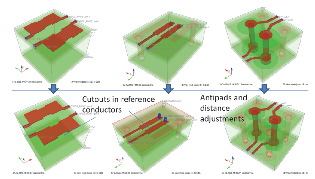
The return loss violates PCIe 5.0 standard mask (indicated by the black line on the bottom two graphs) in this case, and the main reasons for this are the reflections from the component pads, viaholes, and microstrip traces on the top side of the board (indicated by the dips and spikes of the TDR plots of the top graphs). That was also observed during the preliminary impedance continuity analysis in the ERC mode. The link requires optimization that can be also done in Simbeor. Small cut‐outs in the reference conductors below the signal pads can be used to reduce the capacitance of the component pads, and adjustments of distance between the signal viaholes and anti‐pad size can be used to reduce the inductance of viaholes, as illustrated below:

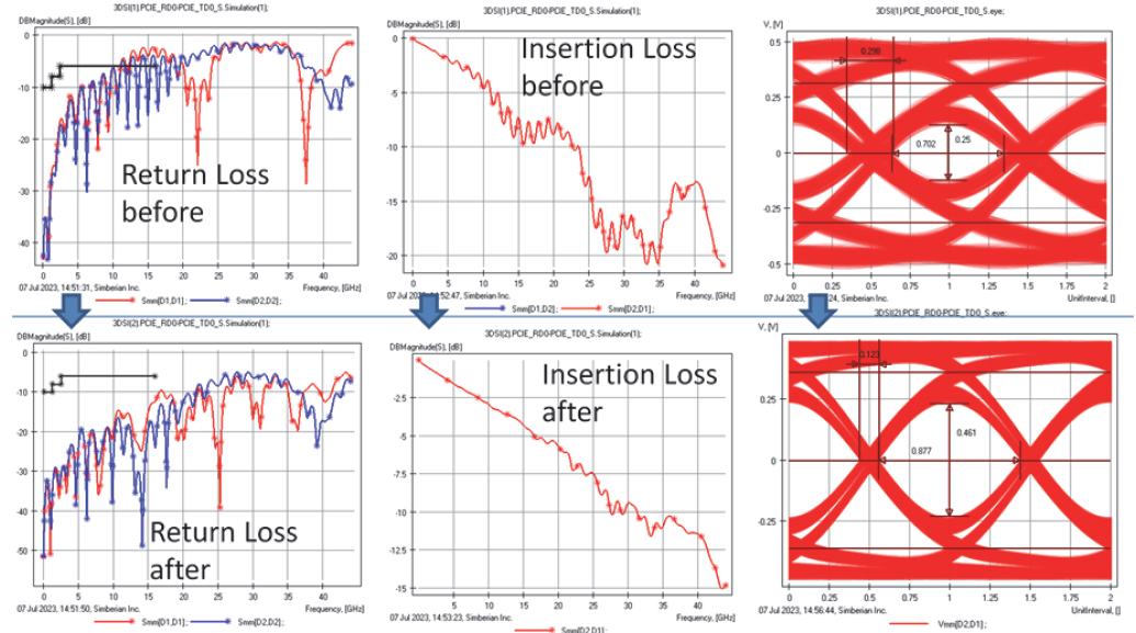
The original geometries of the discontinuities are shown in the top row, and the adjusted, more optimal (or less reflective) discontinuities are shown in the bottom row. The results of these small adjustments are displayed below:

Return and insertion loss and eye diagram of the original link are shown in the top row, and corresponding results for the adjusted link are shown in the bottom row. What a difference such small adjustments make! The link passes the return loss mask (indicated by the black line) and the eye is larger, meaning there is more of a margin for possible random unpredictable effects.
Simbeor SI Compliance Analyzer can be used for control of all types of standard compliance metrics (RL, IL, Fitted IL, ILD, PSXT, MDXT, ICN, ICR, etc.). That includes the crosstalk analysis. Local crosstalk evaluation can be done in ERC mode of SI Compliance Analyzer, as illustrated below:

For a selected link, Simbeor finds all possible aggressor links, then evaluates trace to trace and pad to pad coupling in mV (can be dB or %), assuming 1 V excitation with the rise time specified for the signal. It eliminates all types of geometrical proximity rules.
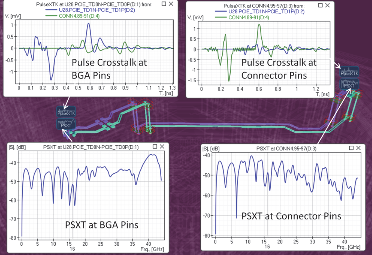
To evaluate the system‐level impact of the crosstalk, Fast SI or 3D SI analysis modes of SI Compliance Analyzer can be used. Fast SI mode includes crosstalk between the traces and pads, wheras 3D SI optionally adds crosstalk evaluation between the vias. The analysis can be done in frequency domain (PSXT, ICR, ICN, MDXT) as well as in time domain (step, pulse crosstalk, or eye diagram with crosstalk), as illustrated below:

The bottom graphs show Power Sum Crosstalk (PSXT) at the BGA and connector pads, and the top graphs show the pulse crosstalk for 32 GT/s signal with 25 ps rise time and 0.5 V excitation. 3D SI analysis is used for this example.
Overview of Simbeor electromagnetic signal integrity software with focus on the recently added SI Compliance Analyzer™ is provided in this article. All types of the signal integrity analyses demonstrated here can be perfromed in Simbeor with just a couple of button clicks. (See a demonstration here). This enables seamless and easy to setup post‐layout analysis automation, with scripting for the whole board as well as optional comparison of the results with the previous iteration of the same design. All critical links on a board can be either be checked in minutes with simulation‐based ERC analysis (all applications), simulated in tens of minutes with Fast SI analysis (DDRx), or simulated in a few hours with the measurement‐validated 3D SI analysis (SerDes). Note that the accuracy of all types of analyses, except the reference integrity, depends on the accuracy of the material models and the accuracy of PCB manufacturing.7,8 Broadband dielectric and conductor roughness models have to be identified before the analysis, and Simbeor is ideal tool for that, too. Four methods are available in Simbeor for the broadband dielectric and conductor roughness model identification. This can be done manually, or automated with Simbeor SDK. The release of Simbeor 2023 further pushes the boundary of possibilities with the extensions in EM solvers, allowing the building of accurate models at frequencies over 50 GHz and enabling new capabilities in SI Compliance Analyzer, leading to an increase in the productivity of PCB designers.
REFERENCES:
- Y. Shlepnev, How Interconnects Work: Bandwidth for Modeling and Measurements, Simberian App Note #2021_09, November 8, 2021.
- Y. Shlepnev, Sink or swim at 28 Gbps, The PCB Design Magazine, October 2014, p. 12‐23.
- A. Manukovsky, Y. Shlepnev, Z. Khasidashvili, E. Zalianski, Machine Learning Applications for COM Based Simulation of 112Gb Systems, Wednesday, January 28‐30, DesignCon 2020
- Y. Shlepnev, Life beyond 10 Gbps: Localize or Fail!, April 13, 2018, Simberian App Note #2018_03, April 13, 2018.
- Y. Shlepnev, How Interconnects Work: Impedance and Reflections, Simberian App Note #2021_11, December 22, 2021.
- Y. Shlepnev, How Interconnects Work: Reflections from Discontinuities, Simberian App Note #2022_01, January 10, 2022.
- M. Marin, Y. Shlepnev, 40 GHz PCB Interconnect Validation: Expectation vs. Reality, DesignCon2018, January 31, 2018, Santa Clara, CA. ‐ the award‐winning paper from DesignCon2018.
- A. Manukovsky, Y. Shlepnev, Effect of PCB Fabrication Variations on Interconnect Loss, Delay, Impedance & Identified Material Models

