

For this extreme measurement example, I selected a simple problem that has been widely published by myself and many others, including past DesignCon papers. The solution is well understood, providing a simple example to illustrate the process.

Figure 1 An example of the very large error created by the cable shield resistance in the traditional 2-port Shunt-Through measurement setup.
The shield resistance error is often much larger than the device we are measuring, as is the case in Figure 1, showing a 500% error. There are three possible solutions to this measurement issue. One possible solution is to calibrate out the error. While this may work, the calibration does not correct the sensitivity, so very small changes in contact resistance of the probes or shield resistance, for example, will result in large measurement errors.
A second option is to use an instrument with floating receivers. Very few vector network analyzers (VNAs) offer such a solution, though the Keysight E5061B is one. This would still be limited to the low frequency side of the instrument which can only measure up to 30 MHz.
A third solution is to break the ground loop at port 2 using a ground isolator: either a transformer isolator, which can resolve the ground loop above a few kHz or a solid-state isolator, which can break the ground loop all the way down to DC.
From one of my own presentations on the 2-port shunt-through impedance measurement error [1].

This equation tells us that the cable shield resistance error is essentially the resistance of the port 1 cable shield divided by the common mode rejection ratio (CMRR) of the isolator. So, we can resolve the error by reducing the shield resistance, such as by using low resistance power delivery network (PDN) cables or by using shorter cables. A second solution is to increase the CMRR of the isolator, either by selecting an isolating transformer with improved coupling or by using a higher CMRR solid-state amplifier. We have identified two specific tools that can reduce the shield error enough for us to make an accurate measurement.
Once this shield error is minimized, the measurement may still not be correct. The next barrier is identified. In this case, it was the connection of the cables to the DUT. The 2-port shunt-through measurement is a 2-port, four-contact point measurement. In the PCB example on the left in Figure 2, the cables first connect to each other, and then connect to the DUT that then connects across the pads to the ground with a low impedance. That very short connection of the cables to the DUT pad is only a two-contact point connection, raising both the resistance and the inductance of the measurement.
What methods can be used to remove this next obstacle? In this case we redesigned the PCB to have a 4-point connection (as shown in Figure 3 on the right), but surely there are other solutions. One solution might be to use a 2-port impedance probe. Another solution might be not to use the SMA connectors, but to solder coaxial cable pigtails to the resistor. There may be other methods of providing four-point contact as well, and this process continues until a solution is identified that can be implemented with equipment that is on hand.

Figure 2 After resolving the ground resistance error, another error appears, and the process continues until all of the obstacles are removed.
With the obstacles removed, the measurement can be performed. In keeping with the extreme measurement theme, I chose to measure a 33 uOhm DUT resistor. The measurement result shows little noise and is flat up until the inductive region of the resistor starts at about 20 kHz.
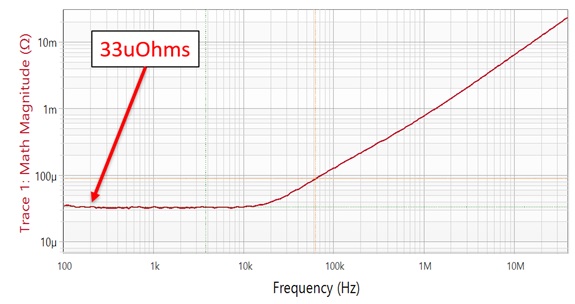
Figure 3 After clearing the identified issues, the measurement of a resistor is performed.
We are not quite finished yet. How do we know that this is the correct result? We need to use another method to perform this measurement to verify it is correct.
Having a DC power supply on hand and an exceptionally low noise digital multimeter (DMM), we can measure the DC resistance using the same connectors the VNA is using. The power supply is set to source 1 Amp into one of the SMA connectors. The low noise DMM is connected to the other SMA connector and the DMM reads 33uV. This is seen in Figure 4. The extreme measurement has now been performed and validated.

Figure 4 A power supply sources 1Amp into one of the SMA connectors the VNA measurement uses, and the DMM is connected to the other SMA connector that the VNA uses. The DMM displays 33uV, confirming the accurate VNA measurement.
A question I am often asked is, “Can I make this same measurement using a 2-port impedance probe?” We can view this as just another obstacle. What new artifacts does the probe introduce that we have not already dealt with?
The probe uses spring pins, and these add resistance in the ground connection. This is similar to the issue presented by a longer cable. The resolutions are the same as before. Shorter cables or greater CMRR or a higher impedance limit.
Another artifact is that the probe introduces coupling that didn’t exist for the 180-degree opposing SMA connectors. This can be resolved using fixture remove calibration and/or isolation calibration.
Using the same cables and the same isolator, the impedance floor is raised a bit, but the example in 5 shows a 180 uOhm measurement using a P2102A 2-port impedance probe.

Figure 5 Using the same cables and isolator, the impedance floor is raised a bit, but this measurement shows a 180uOhm resistor measured using the P2102A 2-port impedance probe.
To summarize this example, we identified the obstacles to the measurement: the shield resistance and the proper connection to the DUT. We identified the two parameters that control the error: the cable shield resistance and the isolator CMRR. We used this to resolve the shield resistance issue.
We redesigned the PCB to clear the DUT contact, but also identified alternate solutions in the event we could not wait for a new PCB.
We performed and validated the measurement using a second method.
We added a new obstacle with the introduction of the 2-port probe pins and identified the limits and options to overcoming the newly introduced issues.
This example was originally presented at DesignCon 2021.
Reference:
[1] Steven M. Sandler, How to measure ultra-low impedance (100uOhm and lower) PDNs, EDICON University 2018