A Teaser Question
I recently received a note from an engineer who asked about a paradox that is often used in prelim exams to trip up EE PhD students. We start with two identical capacitors, one charged to 2 V and the other starting at 0 V. Then we connect them together. This circuit is shown in Figure 1.

The first question is, what is the voltage on each after they are connected together? Of course, the voltages become 1 V on each. Now comes the trick question. What is the energy stored on the capacitors before and after the switch is closed?
The answer is that before the switch, the energy on the charged capacitor is ½ CV2 = 2 Joules. After the switch is closed, the energy stored on both is 2 x ½ CV2 = 1 Joules. What happened to conservation of energy? Where did the extra energy go?
Remember, this is an ideal model. Every element and its properties in this ideal world are mathematically defined. There is no approximation. Where did the energy go?
The resolution of this problem points out a limitation in the ideal world of models. The behaviors of the ideal circuit elements used frequently do not have conservation of energy built into them. They have KCL and KVL built into them. It has I-V relationships that define each element built into them.
In the real world, if you build this circuit, the real wires connecting the capacitors have length and loss, modeled as inductance and resistance. When the real switch is thrown, the real circuit will show oscillations, and the missing 1 Joule of energy will be dissipated in the resistance of the wires.
This is an example of the limitation of the ideal world. It is not the only example. Even without the conservation of energy, there are other paradoxes one can create in the ideal world using KVL and KCL, which trip up engineers all the time.
Don't Try This at Home
When I taught freshmen circuits, I introduced the behavior of ideal voltage sources, as always keeping the voltage across the terminals a fixed, set voltage, an ideal current source as always creating a constant, fixed current through it, and an ideal wire as having no voltage across its ends.
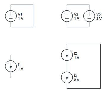
Then, usually on a Friday at the end of class, I leave the students with the circuits shown in Figure 2 and give them the assignment to calculate the voltages and currents in each.
 Figure 2.
 In the ideal world, you can create any circuit you want with any combination of ideal elements. But each of these circuits would cause the universe to blow up. If you try to simulate them in a SPICE simulator, the simulator will return an error.
This is an important example of the difference between the ideal world and the real world. In the ideal world, each element is precisely defined, and the properties of circuits composed of them are mathematically defined. There is no approximation in the ideal world.
Given these rules, there are some combinations that, while legal, will blow up the universe and should be avoided. These limitations should not be a reason to throw out the ideal world of simulations. It just means that these circuits are not part of best practices using a circuit simulation tool.
The ideal world is not the real world. They are different. Every engineer needs to keep the ideal world and the real world clearly separated. The value of the ideal world of circuit elements is only as valuable as our ability to use it to accurately approximate the behavior of the real world.
When using an ideal lossless transmission line to predict the insertion loss behavior of a real transmission line, one can find it accounts for the impact from reflections really well, but not for the loss behavior. When we add the properties of losses in the ideal transmission line, it is still an ideal transmission line; it just has a higher level of complexity and includes the behavior of conductor loss that varies with the square root of frequency, and dielectric loss that includes a frequency-dependent loss.
An even more complex ideal circuit element is a lossy transmission line model that includes a causal model for the dielectric properties that describe the frequency dependence of the Dk and Df terms that obey the Kramers-Kronig relationship.
It is still an ideal model with mathematically precise behaviors.
An even more complex ideal transmission line model that includes two parameters that describe the copper surface texture can be created, which is also causal and includes its impact on conductor loss and phase delay. It is still an ideal circuit element. Some engineers refer to these models as “non-ideal” transmission line models. This is a mistake. If they are used in a simulation tool, they are ideal circuit elements, just more complex than an ideal lossless transmission line element.
It is remarkable that these relatively simple, ideal circuit elements, precisely defined with a few mathematical definitions, predict a simulated behavior that matches the measured behavior of real structures so incredibly well. This is why these virtual prototypes have been called digital twins. When constructed correctly, the virtual prototype’s behavior is a twin of the behavior of a real prototype built.
While there are built-in limitations to the ideal models and circuits, ideal circuit elements are a powerful tool that enables us to explore the real world in virtual prototypes. Engineers can often gain insights and reach an optimized design faster using a virtual prototype than would be possible when building a real physical prototype. This is what best practices are all about: using processes and tools that result in an accurate representation of the real world without blowing up the universe.

