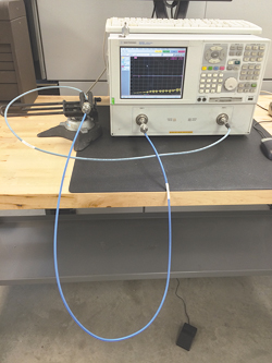
Figure 1 The baseline performance data for the cable being tested (blue outer sheath) is taken with the cable in a U shape.
When discussing RF coaxial cable assemblies, we frequently hear “What is the RF stability of the assembly?” The trouble is, depending on the application, a variety of answers may apply. With this article, we intend to illustrate the value of employing a conservative methodology that closely aligns with published International Electrotechnical Commission (IEC) documents and is tailored to environmental conditions to arrive at test procedures that will absolutely ensure performance in the field. By comparing and contrasting our own San-tron test procedures with those published by the IEC, we hope to demonstrate how a different perspective and approach nets optimal results in the field. We note, however, that the evolution of test protocols that originated within the U.S. military procurement agencies (MIL-STD) and were adopted and updated by the IEC may still develop into more improved practices.
In the process of implementing test procedures, it is essential to first identify the true intent of the testing. One may be to characterize the limiting performance characteristics of the assembly. As a result, the test protocol will require manipulation of the cable to its actual limiting parameters, as opposed to those outlined by the “standard.” For example, these would include dynamic minimum bend radius, maximum torque and the operational thermal limits of the components. Another intent may be to characterize the cable performance within the scope of an operational deployment, such as avionics, outdoor cellular communications or test and measurement. In so doing, it becomes easier to compare alternative solutions and how they will support the intended application.
In this article, we will demonstrate the characterization of test port cables used for vector network analyzer (VNA) and passive intermodulation (PIM) testing. The typical test port cable will range in length from 40 inches (1 m) to 13 feet (4m). Access to the device under test (DUT) varies: it can be located on a test bench, within an environmental chamber, a rack-mounted subsystem, tower mounted system or an aircraft installation. In all of these applications, a test cable will be subjected to repeated bending and twisting. Therefore, we generalize that the cable deployment can be characterized by three basic activities: folding and twisting the cable about a mandrel and low frequency vibration. Regardless of the cable size, it will be subjected to these realistic stresses and strains.

Figure 2 Test setup for the cable folding test.
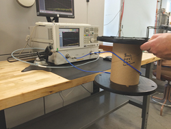
Figure 3 Test setup for the cable twist test.
ASSESSING PHASE STABILITY
To illustrate stability characterization, we use a SRX141™ coaxial cable with eSeries™? connector terminations, the most widely used product from San-tron’s SRX™ series of assembly solutions for both system integration and test and measurement.

Figure 4 Baseline performance of the test cable.
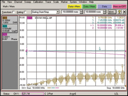
Figure 5 The S21 phase change after the test cable is folded clockwise.
The original prototype for this cable was a fluorinated ethylene propylene (FEP) jacketed cable with silver (Ag) clad copper (Cu) wire braid, Ag clad Cu foil helix, polytetrafluoroethylene (PTFE) dielectric, and Ag clad solid Cu center conductor. Using the cable fold test outlined in the standard for STI 8.2.4-14 A1, the prototype functioned very well. During the cable twist test (STI 8.2.4-14 B1), however, measurements showed instabilities in both insertion loss and PIM performance. Applying the vibration test of STI 8.2.4-14 C2, we saw catastrophic degradation of the cable’s performance over time. The root cause was the physical makeup of the cable loosening under the weave of the braid, generatingPIM signals and varying insertion loss. The failure mode prompted a design review and process upgrade, and we ultimately developed a cable structure that maintains its performance through harsh environments and test protocols.

Figure 6 The S21 phase after the test cable is unfolded. Note that the phase response does not return to the baseline.
For this demonstration, the test cable was an SRX141 cable assembly, rated for PIM applications, that was 60 inches long and terminated with straight eSeries Type N male connectors. The VNA was setup with one test port cable and a full two-port calibration from 10 MHz to 10 GHz usinga Type N calibration kit. After calibration, the test port cable was secured with a 10 lb table vise to prevent the test setup from introducing variation. The test cable was then mated to the VNA and laid out in a U shape, as shown in Figure 1. The test cable was first subjected to five cycles of the cable fold test (see Figure 2) and then five cycles of the cable twist test (see Figure 3). The worst-case results are summarized in Table 1.
The initial phase baseline measurement, shown in Figure 4, established the “zero” line between -0.30 and +0.03 degrees. Folding the sample cable assembly for five repeated cycles in both directions about the 5 inch diameter mandrel resulted in phase shifts with the extreme readings shown in Table 1. The electrical length increased to -0.16 degrees/GHz with clockwise folding (see Figure 5). Unfolding the sample decreased the electrical length to +0.08 degrees/GHz, which is a 0.11 degrees/GHz offset from the baseline measurement. Next, counter-clockwise folding of the sample expanded the electrical length to -0.09 degrees/GHz. Unfolding the sample resulted in +0.26 degrees/GHz (see Figure 6), a 0.29 degrees/GHz offset from the initial condition. The measurements show an asymmetrical variation in phase shift from randomly folding the sample, between -0.16 and +0.26 degrees/GHz. From this data, we can consider the phase stability with folding to be 0.42 degrees/GHz.
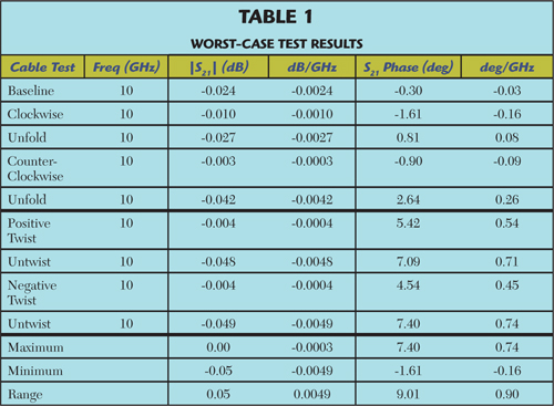
Traditionally, the cable twist test causes greater degradation and is, therefore, performed after the cable fold test. Applying a positive 180 degree physical twist to the test sample yielded a decrease in electrical length to +0.54 degrees/GHz. Relaxing the twist back to the neutral position shifted the phase to +0.71 degrees/GHz. Then applying a negative 180 degree physical twist expanded the electrical length to +0.45 degrees/GHz. Finally, relaxing the twist back to the neutral position decreased the electrical length to +0.74 degrees/GHz.
Notice that when the cables are relaxed, the phase shift does not revert back to zero; we see a range between +0.08 (for the fold test) and +0.74 (for the twist test) degrees/GHz. The fold and twist tests exhibited phase shifts of -0.16 to +0.26 and +0.45 to +0.74 degrees/GHz, respectively. Combining these variations, from -0.16 to +0.74, specifies a phase stability range of 0.90 degrees/GHz.
Multiple mechanisms generate instability. Twisting a cable causes different changes than simply folding the cable. We also see that the effect of twisting decreases the electrical length, where folding can both elongate and constrict phase length. By modeling the intended application and applying tests in a progressive protocol, we can develop a test flow and parameter, such as degrees/GHz, to estimate the measurement uncertainty and cable variation and how the product will perform in the field.
COMPARING CABLE ASSEMBLY TEST METHODS
The above example showed that no single test can identify all latent failure modes. With the initial cable design described previously, the prototype passed the fold test, yet the twist test surfaced an anomaly. The vibration test confirmed that the assembly possessed a latent defect that would manifest failures in the field. By defining a test protocol to evaluate and qualify the design and assembly processes, the SRX™ product line was deployed with performance characteristics never before realized in fully flexible cable assemblies.
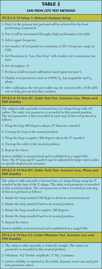
The San-tron test methods are summarized in Table 2. These tests require multiple cycles of physical stress, at least five times to determine if the measured parameters vary over the repeated cycles. If variation is observed, personnel can decide if additional testing is warranted. San-tron has found these tests to be extremely cost effective. Other than the VNA, they require a minimum investment in test fixtures, apparatus and training. They are easily duplicated and can be implemented in the field for on-site testing and validation.
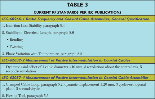
For comparison with the San-tron test methods, Table 3 summarizes the IEC publications. These test methods are also economical and require a minimum of tooling. They are an excellent source for training engineers and test technicians, especially the General Specifications of IEC-60966-1. It offers an overview of RF cable assemblies and performance parameters. However the IEC methodology only requires a single test cycle for the stability validations (paragraphs 8.4 and 8.6) and could be improved by requiring multiple cycles of the physical stresses. More development in the processes of IEC-62037-2 and IEC-62037-4 is warranted.
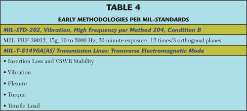
The U.S. military standards (see Table 4) were the genesis of the IEC and San-tron test methods. However, many of the tests are ineffective in identifying potential failure modes, and the required Qualified Products List (QPL) methodology is expensive. It requires significant investments in personnel, test samples, test equipment and the supporting fixtures. Nevertheless, the MIL-STDs define the most comprehensive characterization and are justified for military deployments where lives are at risk.
Conclusion
Adequately testing and qualifying a cable assembly design and assuring product quality in manufacturing requires a test methodology that is tailored to the application and will identify potential failure modes before they can occur in the field. The methodology must subject the cable assembly to multiple cycles of physical stress, including folding, twisting and low frequency vibration. The tests and flow developed by San-tron have proven to achieve these goals –it is cost effective and can be performed in the field.
