
The selection of the output filter inductor is generally chosen using several figures of merit (FOM). Some of these figures of merit are discussed in the datasheet for the switching regulator device. Three key factors are often highlighted for this component selection:
- The inductance value is typically chosen for a ripple current between 10% and 30% of the rated output current.
- The inductor should not be saturated when operated in the maximum current limit or short circuit condition.
- The inductor should be selected to maintain a stable current loop for current mode converters. Incorrect selection can result in sub-harmonic oscillations of the converter particularly when operating 50% duty cycle. This is well understood, but not well specified by most manufacturers.
There are other factors that are often not discussed in datasheets or nearly as well known by design engineers. For example, the inductance value can have an impact on the large signal transient response of the switching regulator. If the inductance is too large, the duty cycle can fall to zero or increase to the maximum duty cycle during a large load current change. In these cases, the feedback loop loses control, and the output voltage excursions will be much larger than expected.
The qualitative nature of the impact of inductance on the current loop stability is well understood. The quantitative current loop stability is generally not specified by the semiconductor manufacturer, nor is the information required to calculate it.
A consideration that is often neglected is the impact of the self-resonant frequency (SRF) or parallel equivalent capacitance, Cp, which is related to SRF.
In this article, I am going to focus on this characteristic - the impact of the inductor SRF on the switching regulator performance. If there is sufficient interest, perhaps I’ll write additional articles related to these other aspects.
Self-Resonant Frequency (SRF)
This is a measure of the internal parasitic capacitance in parallel with the inductor.

Figure 1 - A simplified schematic of an inductor showing the DC resistance, inductance, parallel capacitance, and AC loss resistance.
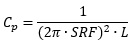
This parasitic capacitance is related to the construction of the inductor and is related to the number of turns, the insulator between turns and the winding type. The SRF of the inductor is the parallel resonance of the inductance and the parallel capacitance, Cp:

Cp can be calculated by rearranging this equation, Solving for Cp:
In many cases, particularly for larger inductance values, the SRF is provided. In the case of low value, high current inductors, it is rarely specified. This is mostly because the Cp is quite high, which is undesirable. For example, consider this FP1308R3-32-R inductor used in our SIC531 DCDC converter demo board. The SRF is not specified, nor is capacitance. This lack of data is not isolated to a manufacturer. Here is another that also do not include SRF or Cp information.
Other manufacturers do provide SRF information. For example, this similar inductor from Bourns includes a 90 MHz SRF specification, though I noted the DCR is much higher in the same size package. Due to the very-high relative DCR, I wouldn’t really consider it to be equivalent despite similar size, inductance and current ratings.
This inductor from Wurth provides an SRF specification of 115 MHz. And, this 300nH inductor from Coilcraft also provides similar inductance and provides a specification of 42 MHz.
If the SRF or Cp are not specified for an inductor being considered, I urge you to measure it yourself. This is a simple measurement with most vector network analyzers (VNAs). Here I used the OMICRON Lab Bode 100 to measure the FP1308R3-32-R, using a 2-port shunt-through method. After calibrating the fixture, using 2-port SOL, the inductor measures 300nH at 1MHz and the SRF measures 18.35 MHz.
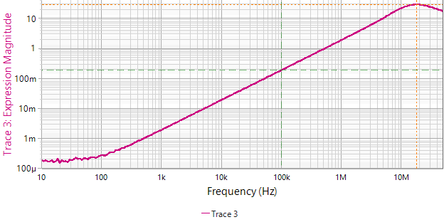
Figure 2- Inductor measurement shows the resonance to be at 18.3MHz. Based on the 300nH inductance, this is a total measured capacitance of 252pF. The inductor mount capacitance is approximately 38pF, resulting in 214pF for the inductor alone.
A custom 300nH toroidal inductor was also designed and manufactured by Leightner Electronics in McKinney Texas for comparison. It is their part number 023-1446. Since we are mostly concerned with the higher frequency inductance and the SRF, a 1-port reflection measurement is performed. The measurement of the Leightner inductor is shown in Figure 3.

Figure 3 - Leightner 023-1446 inductor measurement shows the resonance to be at 400MHz. Based on the 230nH inductance, this is a total measured capacitance of 0.7pF, a factor of 300 lower than the FP1308R3-32-R.
The measurements for several of these inductors are compared in Table 1. All the inductors are approximately 13.5mm x 13mm. In some cases, the inductors were purchased, or received as samples, and measured. In other cases, the datasheet values are listed.
Table 1 - Summary of Inductor Options
|
Part Number |
Manufacturer |
L (nH) 0ADC |
SRF (MHz) |
Cp (pF) |
DCR (mΩ) |
|
FP1308R3-32-R |
Eaton |
320 |
18.3MHz |
214pF |
0.18 |
|
023-1446 (Custom) |
Leightner |
300 |
400MHz |
0.7pF |
0.18 |
|
744309033 |
Wurth |
330 |
158MHz |
3.1pF |
0.17 |
|
SLC1480-301MLD |
Coilcraft |
300 |
46MHz |
39.9pF |
0.18 |
|
SRP-1265 |
Bourns |
320 |
90MHz |
9.8pF |
0.65 |
These inductors all have similar DCR, except for the SRP-1265, and they are all within 315uH +/- 5%. The SRF ranges from 18.3MHz to 400MHz, corresponding with a capacitance range of 0.7pF to 214pF. The data for three of these devices was exported in S1p format and imported into Keysight Pathwave ADS so they can be displayed together. The three measurements are shown in Figure 4.

Figure 4 - Three inductor samples are displayed together. The custom Leightner inductor (GREEN), the Wurth inductor (BLUE), and the designed-in Eaton inductor (RED).
Why it Matters
The switch node of the converter rises from 0V to Vin over the rise time of the MOSFET. For this SIC531 board, the rise and fall time measurements are shown in Figure 5. The faster edge is approximately 1.1ns.
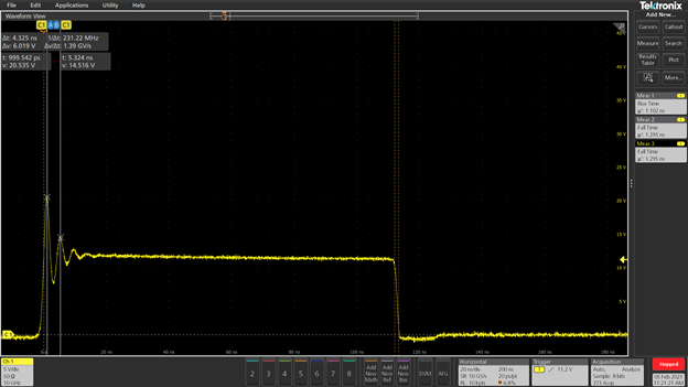
Figure 5 - The SIC531 power module rise and fall time are 1.1ns and 1.3ns, respectively, as measured with a Picotest P2104A 5X ultra-high bandwidth transmission line probe.
The bandwidth of this edge is defined by:

The impedance of the inductor at 318MHz is different for each of the three inductors. The custom inductor is a bit lower in inductance due to the resolution of turns for the desired inductor size. At 318MHz, the edge rate of the switch node, the custom inductor has an impedance of about 60 Ohms; this is almost double the Wurth inductor and nearly a factor of five greater than the designed-in Eaton inductor.
The output ripple and spectrum plot of the DC-DC converter is assessed with the Leightner custom inductor and the designed-in Eaton inductor. The direct comparison is shown in Figure 6.

Figure 6 - The Picotest SIC531 demo board was used to show the output ripple using the designed-in Eaton inductor and the custom-designed Leightner inductor.
The high frequency spike noise, generated by the parasitic parallel capacitance of the inductor and the parasitic series inductance of the output capacitor, is much lower with the custom inductor. The high frequency spectrum (and therefore electromagnetic interference; EMI) is also much lower with the custom inductor. Reducing the parallel inductor capacitance and reducing the series inductance of the output capacitor are both effective at reducing the high frequency spectrum.
Conclusions
There are many considerations in the selection of the output filter inductor. One highly critical parameter is the parasitic capacitance (or SRF) of the inductor. This data is often not published or is poorly defined by the manufacturer.
As always, my recommendation is to measure every component you are considering for your design. It is also worthwhile to compare several potential inductor selections in your circuit, or a representative test fixture, to compare performance and make appropriate tradeoff assessments.
References
- S.M. Sandler, PICOTEST, Measurement Based VRM Modeling, DesignCon 2020
- MASTER THE FUNDAMENTALS OF POWER INTEGRITY AND POWER SUPPLY TESTING.