
Introduction
Addressing CISPR-25 Challenges in IVI Systems through Innovation and Solutions
Our research advances the compliance of In-Vehicle Infotainment (IVI) displays with CISPR-256 automotive electromagnetic compatibility standards7, identifying the Printed Circuit Board Assembly (PCBA) as the primary noncompliance source. We introduced a novel adjustment using conductive foam gaskets to significantly reduce radiative interference, ensuring legal compliance. This approach offers a model for similar diagnostics, contributing to the automotive electronics field by improving electromagnetic interference understanding in IVI systems. The findings propose practical solutions for regulatory adherence, impacting automotive design and testing, and supporting the evolution of more refined Electromagnetic Compatibility (EMC) policies and standards. This research, aimed at enhancing vehicle safety and performance, provides a strategic framework for addressing electromagnetic interference, marking a significant advancement in automotive electronics.
Automotive Electronics Regulations
Radiated emissions regulations for automotive electronics vary globally but share core testing and implementation principles. The FCC in the U.S., ECE Regulation No. 10 in the EU, and CISPR 25 internationally set crucial standards for minimizing interference and ensuring EMC. Japan’s VCCI and China’s CQC contribute to a worldwide regulatory framework, ensuring safety, reliability, and compatibility of automotive electronics across regions, thus supporting global trade and consumer safety.
Radiated Emissions in Automotive Electronic Products
Radiated emissions from automotive electronics pose risks to safety, performance, regulatory compliance, brand reputation, and economic outcomes. Such emissions can lead to health issues for occupants, impair critical vehicle functions like braking and navigation, and disrupt data exchanges in connected vehicles. Compliance with international emission standards is crucial to avoid penalties, product recalls, or bans that can damage a brand’s image and lead to financial losses. Conversely, meeting these standards enhances market competitiveness, consumer trust, and economic benefits, highlighting the importance of rigorous testing and control measures in automotive electronics development.
The Origin of CISPR 25
CISPR 25, established by the International Special Committee on Radio Interference under the International Electrotechnical Commission, is a key international standard for electromagnetic interference (EMI) testing in vehicles, ships, and engines. Created to address radio frequency interference issues identified since 1934, CISPR 25 focuses on automotive and maritime sectors, evolving to manage the complexities of electromagnetic interference with the growth of automotive electronics. It has gained worldwide recognition, being incorporated into various countries’ regulatory frameworks to ensure EMI compliance, and plays a crucial role in mitigating EMI issues globally.
CISPR 25 Certification and Testing Process
CISPR 25, under the International Electrotechnical Commission, is essential for testing EMI in vehicles, ships, and engines, focusing on integrity against electromagnetic disturbances. Globally recognized, it guides regulatory compliance, detailing procedures for conducted and radiated emission tests to ensure EMC. The certification process involves preliminary review, testing in certified labs, and result analysis, with ongoing updates reflecting new technology. Achieving CISPR 25 certification indicates EMC proficiency, aiding in regulatory compliance and commercial success. This standard addresses the challenges of managing radiated emissions in automotive electronics, guiding manufacturers in adhering to EMC standards and solving frequency exceedance issues.
Research Background
The Generation of Radiated Emissions
Radiated emissions arise from electronic devices when current and voltage changes lead to electromagnetic wave propagation, primarily due to rapid digital signal switching and clock oscillations. Power supplies, Wi-Fi, Bluetooth, and mechanical components like motors also contribute to these emissions. Common mode radiation, where current flows uniformly through conductors, is a significant emission source, amplified by antenna-like structures and resonant frequencies. Mitigating these emissions is vital for EMC, ensuring products meet standards and maintain user safety and quality.
Methods for Mitigating Radiated Emissions
Mitigating radiated emissions during electronic device design and testing is crucial for regulatory compliance and product quality. The design phase involves minimizing high frequency component use, employing filters to limit unwanted frequencies, separating sensitive components from high-frequency ones, and implementing comprehensive ground and power planes to reduce emissions. Selecting low-emission components and incorporating impedance matching enhances EMI mitigation.
Testing involves EMC simulations and lab tests to identify and address excessive radiation, using shielding, filtering, and grounding techniques to ensure compliance with standards like FCC, CE, or CISPR.
This paper discusses using conductive gasket materials for shielding against radiated emissions, suggesting that while the exact source of emissions may be speculative, conductive foam installation can effectively mitigate the issue.
The Principle of Shielding
Shielding, using conductive or magnetic materials to encase devices, blocks or absorbs electromagnetic waves from external/internal sources. Material choice, considering conductivity and device proximity, and the electromagnetic wave frequency significantly influence shielding effectiveness. Effective shielding strategies include ensuring material-ground connectivity and minimizing enclosure openings. In this study, conductive foam gaskets effectively reduced high-frequency (555-960 MHz) radiation emissions from PCBA circuit boards, demonstrating shielding’s role in mitigating electromagnetic radiation, crucial for automotive electronics with high-frequency applications.
Shielding acts as a barrier to block electromagnetic field transmission, reducing product emission and preventing external radiation interference. Shielding efficiency, measured in decibels (dB), is the ratio of unshielded to shielded wave amplitude, reflecting absorption losses, surface reflection losses due to impedance discontinuity, and internal reflection losses. This effectiveness demonstrates a method to reduce radiated energy propagation, following methodologies like those proposed by Clayton R. Paul3,4,5, including modifying gaskets to prevent emission leaks.
Experimental Design
Testing Procedure for Radiated Emission Frequency Bands
Radiated emissions testing for automotive electronics mandates simulating real-world vehicle conditions, documenting operational parameters like load and voltage, and specifying device orientation in the test plan. Measurements need vertical polarization for frequencies up to 30 MHz and both polarizations beyond that, up to 2500 MHz, as per CISPR 25:2016. Recommended antennas include the Rod Antenna for VHF/UHF frequencies, Biconical for wide-band use, Log-Periodic for its broad range and directionality, and Horn Antenna for high gain in microwave bands. This structured approach ensures consistent, safety-compliant testing across the automotive industry.
| Rod | Biconical | Log-Periodic | Horn | |
| Frequency | VHF-UHF | Broad | Broad | High |
| Directivity | Omni | Variable | Directional | Highly |
| Usage | Basic Comms | EMC Tests | Spectrum | Radar |
Table 1. Antenna characteristics and applications.
Radiated Interference Limitations – ALSE Method
According to the CISPR-25 standard, the Absorber Lined Shielded Enclosure (ALSE)8,9 method for measuring radiated interference includes five distinct categories of limitations, ranging from Class 1 to Class 5. Each class has its specific radiated interference limits, which are clearly outlined in the respective tables. Briefly:
- Class 1 represents the most lenient category, suitable for scenarios less sensitive to radiated interference
- Class 2 imposes stricter limitations than Class 1 and is commonly used for general vehicle components and modules
- Class 3, a medium-level restriction, is often considered the minimum acceptable standard by most vehicle manufacturers for passing tests
- Class 4 includes more stringent limitations for applications that are particularly sensitive to radiated interference
- Class 5, the most rigorous category, is reserved for special applications with extreme sensitivity to radiated interference.
These classification levels enable vehicle manufacturers and suppliers to choose suitable restrictions for their needs, ensuring radio system stability across different environments.
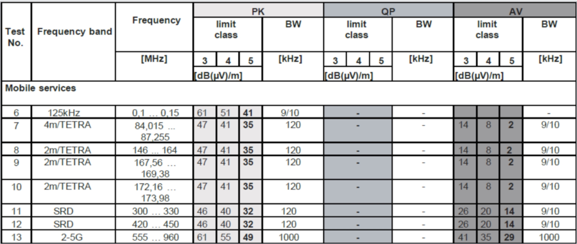 Figure 1. Examples of limits for radiated disturbances, ALSE method.
 Figure 2. Log-periodic antenna.1
Most opt for at least a Class 3 level to pass tests. The study aims to confirm if the 555-960 MHz frequency band meets CISPR-25 standards, emphasizing the importance of these classes in maintaining compliance and system reliability. Specifically, the 555-960 MHz range, part of the broader 200 MHz to 1 GHz spectrum, requires a Log-Periodic antenna for electromagnetic interference testing.
When measuring specific frequency bands, we have designed the measurement environment2 and chosen the appropriate antenna in accordance with the CISPR 25 regulations. The setup concept for the measurement environment is illustrated in Figure 3. Given that our measurement frequency band is 555-960 MHz, and the chosen Log-Periodic antenna operates within the range of 200 MHz to 1 GHz, we opt for this type of antenna for our measurements.
The antenna setup involves meticulous positioning and orienting of the antenna to maximize testing accuracy, specifying the distance between the antenna and the Equipment Under Test (EUT), and detailing the frequency range covered by the log-periodic antenna. Additionally, the usage scenarios for vertical and horizontal polarization are outlined, which may vary depending on the testing frequency range. All necessary measuring instruments, like spectrum analyzers and cables, are listed with guidance on their connections.
The test environment may also be described with specific requirements, such as anechoic or low-reflection chambers, to ensure consistent and comparable test results across different testing sites and conditions. It is important to note that this is a generalized explanation and the specifics can vary with different editions or revisions of the CISPR-25 standard. The setup outlined provides a reference standard for experimenters to ensure reliable testing outcomes.
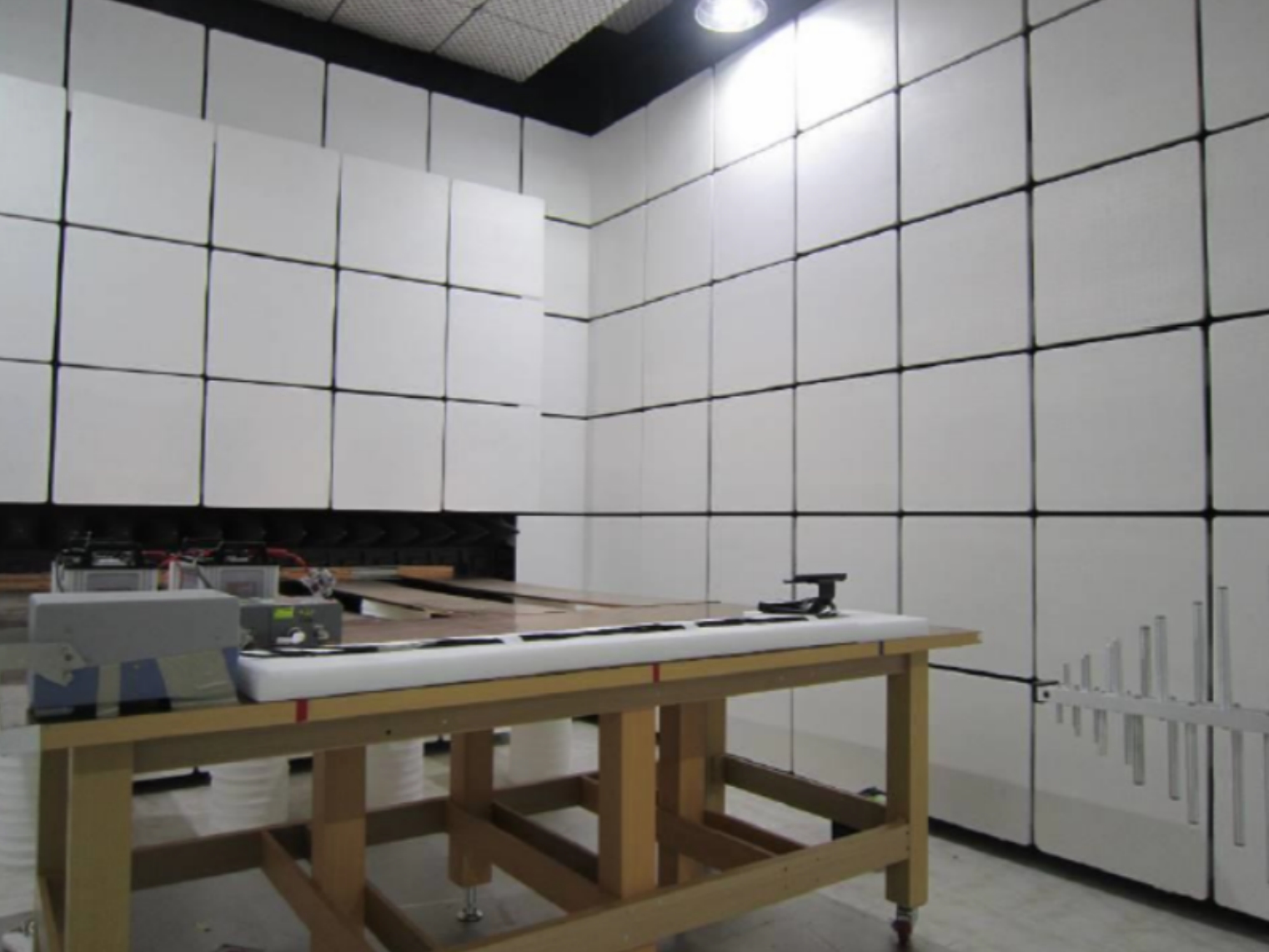 Figure 3. Diagram of log-periodic antenna radiated radiation measurement environment setup.
Frequency Range |
Recommended Antenna |
Polarization |
150 KHz to 30 MHz |
Monopole |
Vertical |
30 MHz to 300 MHz |
Biconical |
Horizontal & Vertical |
200 MHz to 1 GHz |
Log-Periodic |
Horizontal & Vertical |
30 MHz to 1 GHz |
Broadband |
Horizontal & Vertical |
1 GHz to 2.5 GHz |
Horn |
Horizontal & Vertical |
Table 2. Antenna selection for EMI testing.
Experimental Results
Measurement Results of Radiative Emissions Prior to the Manual Adjustment and Installation of Conductive Foam
In the radiation emission tests spanning the frequency range of 555-960 MHz, as depicted in Figure 4, discrepancies from the standard limits were identified, particularly in specific frequencies. Notably, the average (AVG) radiation levels at the 806.5 MHz frequency exceeded the prescribed limit by 2.51 dB, and at 924 MHz, the exceedance was 0.69 dB.
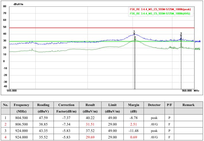 Figure 4. Frequency 555-960 MHz exceeds limits by 2.51 dB on average.
| Equipment Name | Manufacturer | Model |
| EMI Test Receiver | Keysight | N9038A |
| EMI Test Receiver | Rhode & Schwarz | ESR 7 |
| Pre-Amplifier | EMEC | EM330 |
| Pre-Amplifier | EMCI | EMC051845SE |
| Coaxial Cable | Huber and Suhner | SUCIFLEX |
| Coaxial Cable | Huber and Suhner | SUCIFLEX |
| Monopole Antenna | SCHWARZBECK | VAMP9243B |
| Biconical Antenna | SCHWARZBECK | VHB9124/BBA9106 |
| Log-Periodic Antenna | SCHWARZBECK | VULP9118A |
| Horn Antenna | SCHWARZBECK | BBHA9120J |
| LISN | FCC | FCC-LISN models |
| LISN | FCC | FCC-LISN models |
| Loop Antenna | SCHWARZBECK | FMZB 1513-60 |
| Software | EZ-EMC5A2 | NA |
Table 3. EMI chamber equipment list.
To address these non-compliance issues, especial focus has been placed on the 806.5 MHz frequency, where the deviation was most significant. Drawing from the stringent criteria set forth in Class 5, as outlined in Figure 1, both peak and AVG emission limits are defined at 49 dBμV/m and 29 dBμV/m, respectively. Any frequency exceeding these thresholds is considered a fail and necessitates remedial actions. Furthermore, Figure 1 delineates more lenient criteria under Class 3 and Class 4, with peak limits of 61 dB/m and 55 dB/m, and average limits of 41 dB/m and 35 dB/m, respectively. The test details reveal that for AVG emissions, the 806.5 MHz frequency showed a reading of 31.51 dB/m, surpassing the limit by 2.51 dB, and the 924 MHz frequency registered 29.69 dB/m, marginally over the limit by 0.69 dB. For peak emissions, the frequencies of 804.5 MHz and 924 MHz recorded 40.22 dB/m and 37.52 dB/m, respectively, both well within the Class 5 peak limit, thereby not exceeding the stringent limit of 49 dBμV/m.
Near-Field Probe Measurements Have Detected High Noise Levels at the Base of the Display
Using a near-field probe on automotive electronic screen circuit boards, we detected excessive EMI potentially affecting screen function, with notable spikes in certain frequencies suggesting circuit instability. Despite recording eak” values, they only indicated high noise levels without providing detailed insights, hinting at issues such as unstable power, inadequate grounding, or component failure. We suggest additional tests to pinpoint the noise source and address it effectively.
Resolution Strategy: Add Manually Modified Conductive Foam to the Bracket
In our study, we mitigated chassis noise by manually adding conductive foam, made by encasing foam in conductive fabric. Initial results showed an 8 dB noise reduction, indicating this method’s potential effectiveness in noise mitigation.
Strategy for Implementing Conductive Foam
The identification of oscillation areas is highlighted in Figure 4, where potential oscillations were observed in the region outlined in red after mounting the PCBA within the chassis. Prior to the assembly of the chassis, this specific area did not exhibit high noise levels. It is conjectured that the noise increase in this area could be due to the assembly of the chassis, which contains metal components. In addressing this issue, as documented in Figure 5, an experimental design was implemented where conductive foam was used to encapsulate the metal area. Following this intervention and subsequent measurements with a near-field probe, a notable reduction in noise by 8 dB was observed. This demonstrates the effectiveness of employing conductive foam in reducing noise in areas prone to oscillation.
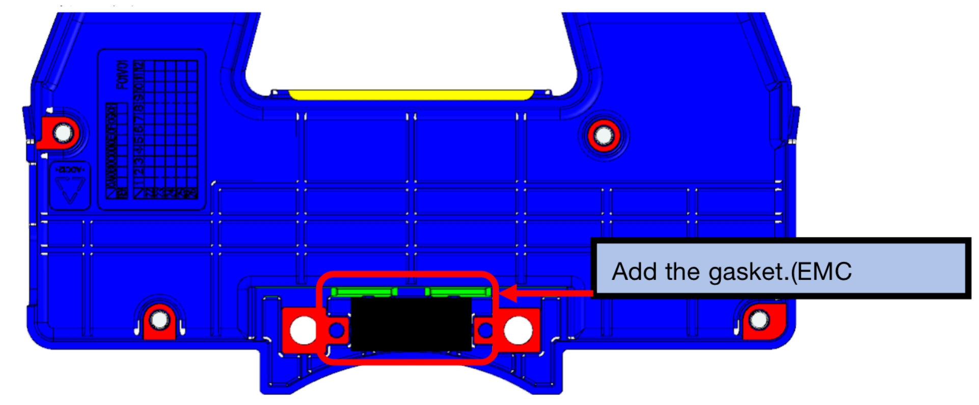 Figure 5. Schematic diagram of conductive foam placement.
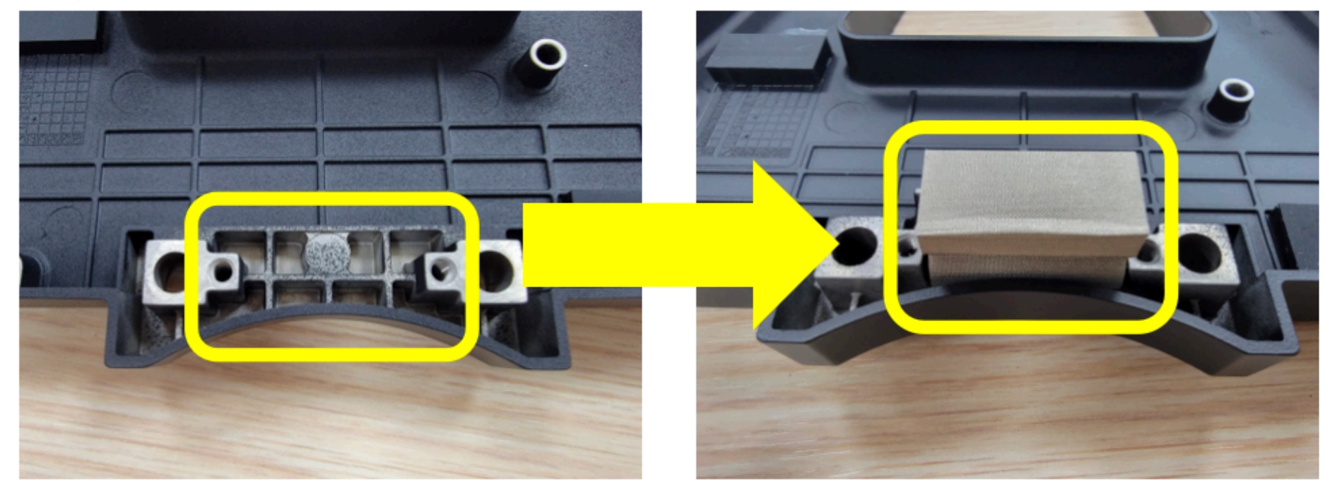 Figure 6. Actual image displaying before and after implementing conductive foam.
The Integration of Conductive Foam into the Bracket Resulted in an 8 dB Improvement in the Measurement Results
Initially, radiation at the 806.5 MHz frequency exceeded limits by 2.51 dB, prompting the use of conductive foam as a remedy. Retesting revealed an 8 dB improvement at the 790 MHz band, significantly better than the original levels and confirming the foam’s effectiveness across multiple frequencies, including the originally problematic 806.5 MHz and 924 MHz. Despite all intervals passing upon retest, caution was advised due to values nearing failure thresholds. Notably, retests at 806.5 MHz and 924 MHz showed substantial compliance with CISPR-25 standards, which prescribe limits for various types of EMI measurements to ensure automotive components’ operational integrity without causing or suffering interference. This underscores the conductive foam’s role in aligning with these critical specifications, highlighting a targeted approach to mitigating EMI within the automotive sector.
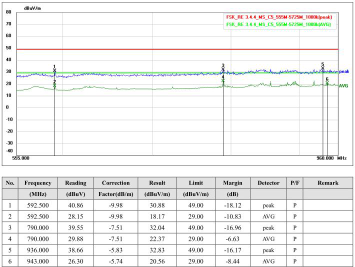 Figure 7. 8 dB improvement in 555-960 MHz range.
Conclusion
This study identifies an issue with radiation exceeding the CISPR-25 standard limits by 2.51 dB within the 555-960 MHz frequency range in automotive electronic vehicle information system screens, pinpointing the screen’s PCBA circuit board as the primary source of radiation. A significant improvement was achieved by manually modifying the Gasket with conductive foam, effectively reducing the radiation levels.
The excess radiation presents a compliance threat, potentially preventing the product from legally entering the market, affecting both the development cycle and costs. The identification of the PCBA circuit board as the main radiation source underscores the necessity for design improvements focused on this area.
However, the study’s scope is limited to the 555-960 MHz frequency range and is specific to a particular model of automotive electronic screens, which may not be universally applicable across other models or brands. Future research should encompass a broader frequency range and delve deeper into why the PCBA circuit board is a significant radiation source, considering more comprehensive improvement strategies. Additionally, evaluating other radiation reduction technologies or materials beyond Gasket conductive foam and conducting experiments on a larger scale across various automotive electronic devices would validate the study’s applicability. This research lays the groundwork for addressing specific radiation issues, offering an effective solution, with further investigation needed to ensure compliance with regulations.
REFERENCES
- T. Hegarty, “An overview of conducted EMI specifications for power supplies,” Texas Instruments, Tech. Rep., June 2018.
- CISPR, “Vehicles, boats and internal combustion engines–radio disturbance characteristics–limits and methods of measurement for the protection of on-board receivers,” CISPR, Tech. Rep., October 27 2016.
- C. R. Paul, Introduction to Electromagnetic Compatibility, 1st ed. John Wiley Sons, 1992.
- M. P. Robinson, T. M. Benson, C. Christopoulos, J. F. Dawson, M. D. Ganley, A. C. Marvin,S. J. Porter, and D. W. P. Thomas, “Analytical formulation for the shielding effectiveness of enclosures with apertures,” IEEE Trans. Electromagn. Compat., vol. 40, pp. 240–248, Aug 1998.
- M. P. Robinson, J. D. Turner, D. W. P. Thomas, J. F. Dawson, M. D. Ganley, A. C. Marvin, S. J. Porter, T. M. Benson, and C. Christopoulos, “Shielding effectiveness of a rectangular enclosure with a rectangular aperture,” Electronics Letters, vol. 32, pp. 1559–1560, Aug 1996.
- IEC, International Special Committee on Radio Interference (CISPR) Guidance for Users of the CISPR Standards, February 2015.
- UNECE, “Uniform provisions concerning the approval of vehicles with regard to electromagnetic compatibility,” Regulation No. 10.
- C. F. M. Carobbi and D. Izzo, ”Evaluation and Improvement of the Reproducibility of CISPR 25 ALSE Test Method,” in IEEE Transactions on Electromagnetic Compatibility, vol. 60, no. 4, pp. 1069-1077, Aug. 2018
- C. Carobbi and D. Izzo, ”Reproducibility of CISPR 25 ALSE test method,” 2017 IEEE International Symposium on Electromagnetic Compatibility Signal/Power Integrity (EMCSI), Washington, DC, USA, 2017, pp. 57-62