
Future data center and high-speed computation require faster connectivity to meet the increasing set of applications and bandwidth. IEEE and OIF have developed 106-112 Gbps per lane electrical interface specifications P802.3ck1 and CEI-112 G2 for the 400 GbE system. To meet the next-generation system bandwidth requirement, industry and standard bodies recently kicked off new projects aiming at 800 GbE or even higher speeds beyond 1 TbE. So what comes next beyond 112 Gbps for electrical interfaces over copper (Cu) channels? Will it be 224 Gbps?
The historical evolution of SerDes IO bandwidth is represented in Figure 1. From 1 Gbps in 2000, to 100-112 Gbps in 2018, the SerDes IO data rate doubles every two to three years. Up until 2012, with rates increasing to 25-28 Gbps, the backplane reach was maintained up to 40 in. with acceptable system performance. The relative power per bit (PJ/bit) has reduced regardless of the growth of the data rate and more complicated equalization schemes, such as multi-tap decision feedback equalizer (DFE), that have been adopted in the reference receivers.

Fig. 1 SerDes data rate, reach distance, and power efficiency vs. year of introduction.
Ideally SerDes reach is maintained or extended even when the link rate goes up, while at the same time the design goal is to continually reduce the power per bit. Unfortunately, we start seeing the undesirable dipping point for reach distance and power efficiency occur at the transition from 25-28 Gbps to 56 Gbps, when the modulation scheme changes from non-return to zero (NRZ) to pulse amplitude modulation level 4 (PAM4). Higher level modulation provides better spectral advantage, but it increases the implementation complexity and the system requirement of forward error correction (FEC). Therefore, the continued performance demand of higher link rates over passive Cu links poses some unique engineering challenges to overcome shortages of power efficiency, reach distance, latency, and overall cost.
Analysis of Cu Serial Links at 224 Gbps
To study the feasibility of 224 Gbps transmission over Cu channels, three aspects will be discussed:
- Alternative modulation schemes
- Ideal equalization and implementation allowances
- Advanced FEC options
From Figure 2 we can see that NRZ or even PAM4 becomes impossible to support the IEEE802.3ck 112 G reference channels3 if the data rate doubles to 224 Gbps because the channel insertion loss (IL) will be too large at the Nyquist frequency (56 GHz for PAM4). Higher level modulation schemes beyond PAM4 could be worth considering with a reduced baud rate equal to 224 Gbaud/log2(L), where L=2, 3, 4, 5, 6, 7, 8, … is the PAM modulation signal level. Undoubtedly channel IL becomes more tolerable at lower baud rates.

Fig. 2 Frequency responses for IEEE P802.3.ck 112 G golden reference channels.
The higher level PAM modulation offers larger unit interval and reduced bandwidth, but at the expense of a higher signal-to-noise ratio (SNR) requirement. The symbol error rate DER0 is calculated as

Figure 3 shows that higher modulation levels require higher slicer SNR to achieve a certain DER0. For example, the required SNR at the SerDes slicer to achieve 1e-6 DER0 are 13.54 dB, 20.67 dB, and 26.96 dB for NRZ, PAM4, and PAM8 modulation schemes, respectively. The trade-off between spectral benefit and SNR penalty make the modulation scheme selection more complicated, requiring detailed analysis.

Fig. 3 Required SNR to achieve target DER0 for different modulation levels.
To study the performance trade-off for different modulation schemes, let’s start with the upper bound of SerDes performance, the Salz SNR4 with an ideal DFE receiver. Figure 4 is the block diagram of a link model and Table 1 is the modeled impairments and their values added in the Salz SNR calculation.

Fig. 4 Block diagram of a link model for Salz SNR calculation.

Chip-to-Module Interfaces
When looking at 224 Gbps per lane electrical interfaces, a key factor is whether the chip-to-module very-short-reach (VSR) interface is feasible. If the answer is yes, then many of the current system and application options will be available for the next-generation also.
For the next analysis, a set of twenty different current 112 Gbps VSR channels3 are selected for simulation at 224 Gbps. Figure 5 shows their IL; return loss, figure of merit ILD (FOMILD); cross talk, integrated near-end crosstalk noise (NEXT ICN); and integrated far-end crosstalk noise (FEXT ICN) with 112 Gbaud (224 Gbps) PAM4 modulation. These VSR channels have IL 15 to 40 dB with the doubling data rate of 224 Gbps.
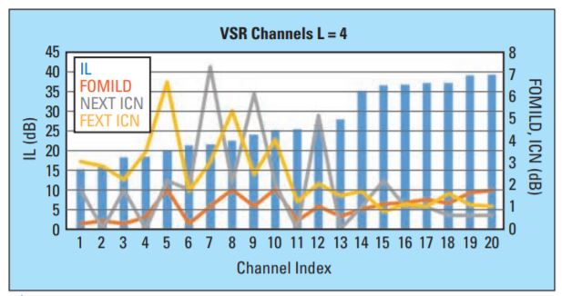
Fig. 5 VSR channels and their channel losses and crosstalk values for 224 Gbps with L=4 (PAM4).
Comparing Salz SNR and SNR margin = Salz SNR – slicer SNR requirement (shown in Figure 3) for different DER0 targets, 1e-3, 1e-4, 1e-5, and 1e-6, with L=4 (PAM4) in Figure 6, we can see that the 1e-6 DER0 target is very difficult to meet for most channels with the PAM4 modulation scheme and a margin above 0 dB. Relaxing the DER0 target to 1e-4 or 1e-3 can significantly improve SNR margins by around 2 to 4 dB. In a later section, more advanced FEC schemes will be discussed to compensate for the relaxed DER0 target.
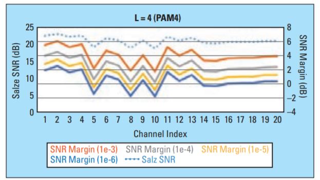
Fig. 6 Salz SNR and SNR margins for different DER0 targets.
In Figure 7, the calculated SNR margins for different modulation schemes L=4, 5, 6, 7, 8 are compared. We can see that L=5 (PAM5) provides the best SNR margin while L=8 (PAM8) is the worst among all modulation schemes. L=4 (PAM4) is slightly worse than PAM5.

Fig. 7 SNR margins for DER0=1e-4 with modulation levels L from four to eight.
It is worth noting that the Salz SNR is upper bound on performance and an implementation allowance must be made for the limitations of practical receivers for circuit noise and distortion, receiver jitter, quantization effects, and finite-length filters, as these are not modeled in the Salz SNR calculation. The value of implementation allowance heavily depends on the individual SerDes architecture and circuit design.
While an implementation allowance value is not proposed in this paper, we may leverage the value of 3 dB as the channel operating margin and can see that some current VSR channels are feasible to operate at 224 Gbps link rate with a PAM4 or PAM5 modulation scheme with a relaxed DER0 target of say, 1e-4 or 1e-3. The feasibility of a 224 Gbps chip-to-module electrical interface is therefore promising to enable pluggable optics. However, it will come with some costs (and differences relative to 112 Gbps) that chip designers and system integrators need to carefully consider, such as complexity, power efficiency, and FEC latency. Some of these costs could be reduced if channels continue to improve over time.
In Package Optics
Besides pluggable optics, in package optics (IPO) is drawing attention for next-generation systems as well. Next we investigate the 224 Gbps die-to-die or package-on-package (XSR) electrical interface proposed for IPO. Figure 8 shows a selection of XSR channels. These XSR channels have IL larger than 10 dB with the doubling data rate of 224 Gbps.

Fig. 8 Die-to-die/package-on-package channels and their SNR margins with different modulation schemes for DER0=1e-6.
To allow simpler and/or lower latency FEC, the XSR DER0 target is normally a few orders of magnitude lower than VSR. From SNR margins for different modulation levels L=4, 5, 6, 7, 8 with DER0=1e-6, we can see that PAM4 modulation provides the best performance for those XSR channels running at 224 Gbps.
Cabled Backplanes
Lastly, long reach (backplane and Cu cable) channels are studied and the results are shown in Figure 9. Unfortunately, due to high channel loss or/and crosstalk, none of the PAM modulation schemes obtain sufficiently good SNR margin. Without significant channel improvement, more complicated modulation schemes such as passband modulation, multiple carriers, or bi-directional transmission have to be considered, but they are less likely to enable power efficiency improvement.

Fig. 9 Long reach channels and their SNR margins with different modulation schemes for DER0=1e-4.
Besides modulation and equalization schemes, FEC is an essential part of a solution for a PAM system.5, 6 Currently Reed Solomon codes have been widely adopted in 56 Gbps or 112 Gbps electrical interfaces. For Ethernet applications, the frame loss ratio (FLR) is normally used as the system performance metric.
Figure 10 shows FLR vs. SNR of different RS codes for PAM4 modulation over additive white Gaussian noise channels (AWGN). Coding gain is the key performance measure for the FEC and it is defined as the reduction in the SNR required at SerDes slicers to achieve a specific BER (or FLR) of a coded system. For a system BER target of 1e-15, KR4 FEC RS (544, 528, 7) and KP4 FEC RS (544, 514, 15) have coding gains of 6 dB and 7.4 dB over uncoded systems. This additional coding gain is achieved at the expense of higher coding complexity and latency of hundreds of nano-seconds (ns).
In designing FEC for error control, it is desired to minimize the SNR required to achieve a specific system BER. A theoretical limit on the minimum SNR required for a coded system with code rate R to achieve error-free transmission (or an arbitrarily small BER) can be derived based on Shannon’s noisy coding theorem.7 This theoretical limit (often called the Shannon limit) simply says that for a coded system with code rate R, error-free transmission is achievable only if the SNR exceeds this limit. As long as the SNR exceeds this limit, Shannon’s coding theorem guarantees the existence of a (perhaps very complex) coded system capable of achieving error-free transmission.
The red dotted line in Figure 10 shows the Shannon limit for a PAM4 system with R= 514/544. We can see that the current KP4 FEC is about 4 dB away from the Shannon limit. This is good news. This gap can be reduced by using a longer and more powerful FEC such as a long RS (1023, 867, 28) code, or/and with soft-decision maximum likelihood detection algorithms. High coding gain and Shannon limit-approaching FEC codes, such as low density parity check codes and Turbo product codes, are already considered for long-distance optical transmission systems.8 For next-generation 800 GbE or beyond, electrical interfaces could also leverage optical system work by deploying higher coding gain FECs if needed, but with the cost of coding latency and complexity.
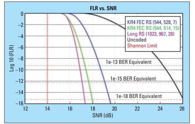
Fig. 10 FLR vs. SNR for uncoded and coded PAM4 system over AWGN channels.
Conclusion
From the ideal DFE receiver Salz SNR performance at 224 Gbps over XSR and VSR channels and the Shannon limit of a coded PAM4 system, we can conclude that electrical interfaces will continue to be viable after 112 Gbps. PAM4 or PAM5 performs better than other higher level modulation schemes such as PAM8. Even with practical implementation allowances, die-to-die, package-on-package, and chip-to-module interfaces are high likely feasible. Long reach electrical interfaces could be very challenging to operate at 224 Gbps within reasonable cost and power efficiency. Promising VSR and XSR results enable pluggable optics and IPO applications at the next speed node. Last but not least, the efficiency of modulation, equalization, and the cost of more advanced FEC are the key to next-generation success.n
References
1. “IEEE 802.3 100 Gb/s, 200 Gb/s, and 400 Gb/s Electrical Interfaces Task Force,” February 2019, http://www.ieee802.org/3/ck/index.html.
2. “OIF CEI-112 G XSR, VSR, MR, and LR Working Group,” https://www.oiforum.com/technical-work/current-work/.
3. “IEEE P802.3ck Task Force – Tools and Channels,” March 2020, http://www.ieee802.org/3/ck/public/tools/index.html.
4. J. Cioffi, and et. al., “MMSE Decision-Feedback Equalizers and Coding-Part I: Equalization Results,” IEEE Trans. on Comm., Vol. 43, No. 10, October 1995.
5. C. Liu, “What is FEC, and How Do I Use It?” Signal Integrity Journal, https://www.signalintegrityjournal.com/articles/1284-what-is-fec-and-how-do-i-use-it.
6. C. Liu, “100+ Gb/s Ethernet Forward Error Correction (FEC) Analysis,” DesignCon 2019.
7. C. E. Shannon, “A Mathematical Theory of Communication,” Bell Syst. Tech. J., July 1948, pp. 379–423 (Part 1); pp. 623-56 (Part 2).
8. G. Tzimpragos, and et. al., “A Survey on FEC Codes for 100G and Beyond Optical Networks,” IEEE Communications Surveys & Tutorials, Vol. 18, Issue 1, 2016.
Published in the SIJ July 2020 Print Issue, Design Tips: Page 34.